
Industrial engineering
Crane Runway Design and Hoist Beam Engineering
Crane runway design for bridge cranes, monorails and jibs, with impact, fatigue and deflection checked and drawings sealed by a licensed PE.
- Stamped by a PE licensed in your state
- Drawn to IBC, IRC and local amendments
- Plan-check comments answered
Support structures that keep loads moving safely overhead
An overhead crane is only as safe as the steel that carries it. Runway girders, columns, monorail beams and hoist beams see repeated moving loads, impact when loads are lifted and stopped, and sideways and lengthwise forces as the crane travels and the trolley moves. Crane runway design has to account for all of it, and for fatigue that ordinary building beams never experience.
PE Engineer designs support structures for top running and underhung bridge cranes, gantry rails, monorails, jib cranes and fixed hoist beams. We size the runway girders and rails, check the building columns and frames that carry them, design brackets, stops and connections, and engineer foundations for freestanding runways and jib cranes. When a crane is being added to an existing building, we evaluate whether the existing frames can carry it and design the reinforcing or independent structure when they cannot.
We work from the crane manufacturer’s wheel loads, spans, capacity and service class. Every design is sealed by a Professional Engineer licensed in the state where the facility is located, ready for permit, fabrication and installation.
What you receive
- Runway girder and rail design
- Column, bracket and frame checks
- Monorail and hoist beam sizing
- Crane stop and connection details
- Foundation design for jibs and freestanding runways
- PE stamped calculations and drawings
Crane and hoist structures we design
From a single trolley beam over a workbench to a multi-bay runway system, we design the steel and foundations that carry the lift.
Top running bridge crane runways
Runway girders, rails, rail clips and corbels or brackets on building columns, designed for wheel loads, impact, lateral thrust, longitudinal force and fatigue.
Underhung crane runways
Runway beams that hang from roof framing or a support structure, with lower flange bending, hanger connections and the roof's capacity to carry the crane all checked.
Freestanding runway structures
Independent columns, girders and bracing for buildings that cannot carry a crane, with foundations and anchorage designed for the full crane load and lateral forces.
Monorails and trolley beams
Straight and curved monorail beams for hoists and trolleys, including switches, end stops and supports from existing steel or new framing.
Jib cranes
Wall-mounted and freestanding jib cranes, with the mast, boom, wall bracket and the large overturning moment at the foundation designed or checked for your installation.
Hoist beams and lifting points
Fixed hoist beams, lifting lugs and roof-mounted lifting points for maintenance on pumps, motors and equipment, with load rating and marking information on the drawings.
How crane runway design differs from ordinary beams
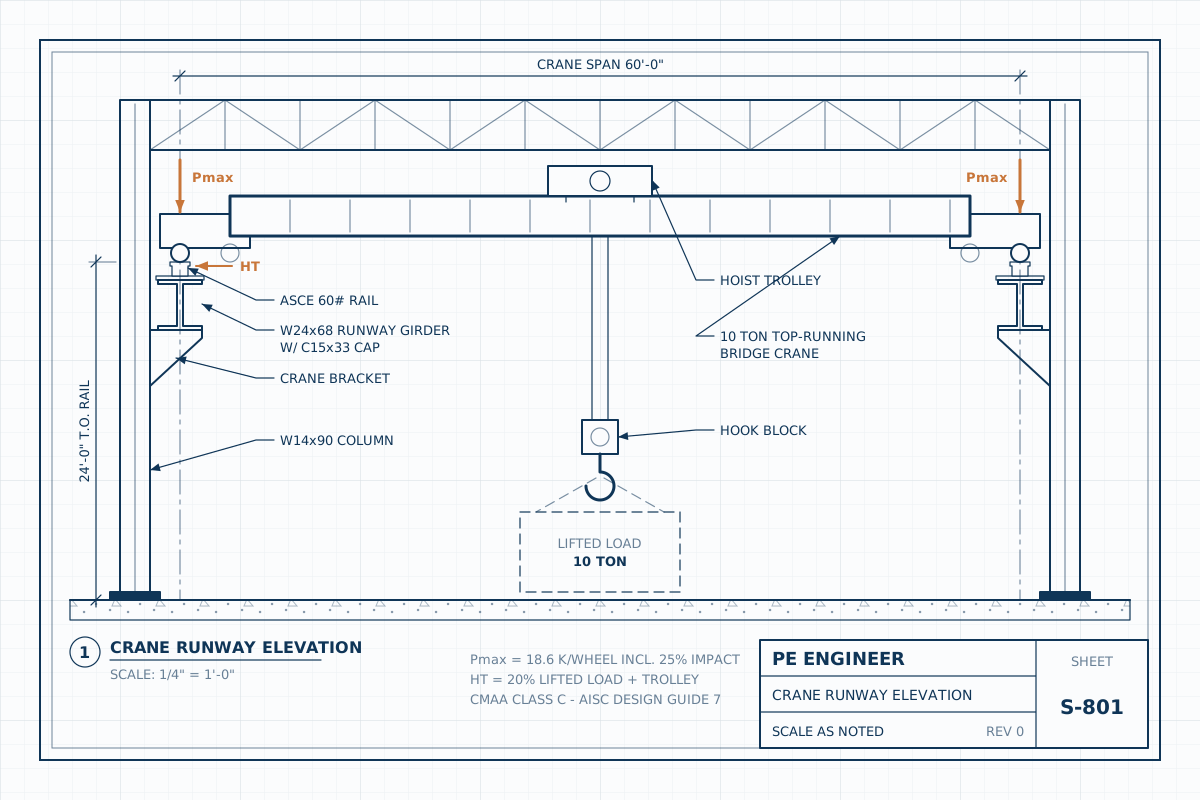
A typical building beam carries a mostly static load. A crane runway girder carries a heavy wheel load that moves along its length, is applied and removed thousands of times, and arrives with dynamic effects. ASCE 7 defines the crane loads that apply to the support structure:
- Vertical impact, an increase in the maximum wheel loads that depends on the crane type, such as 25 percent for powered cab-operated or remotely operated bridge cranes and 10 percent for powered pendant-operated bridge cranes.
- Lateral force from trolley acceleration and braking, taken as 20 percent of the sum of the rated capacity and the weight of the hoist and trolley, applied at the top of the rail.
- Longitudinal force from bridge acceleration and braking, taken as 10 percent of the maximum wheel loads.
Deflection limits for runway girders are much stricter than for floor beams, because excessive deflection or sway causes the crane to bind, skew or wear rails and wheels quickly. AISC Design Guide 7, Industrial Buildings: Roofs to Anchor Rods, gives widely used guidance on runway serviceability limits that tighten as the crane’s service class increases.
Fatigue is the other major difference. Repeated loading can crack welds and connections long before the steel reaches its static strength. We evaluate fatigue under AISC 360 for the number of load cycles the crane’s service class implies, and detail connections, stiffeners and welds to avoid fatigue-sensitive details.
Crane classifications and the data we need
Crane manufacturers classify cranes by service class under CMAA specifications. CMAA 70 covers top running bridge and gantry cranes of multiple girder type, and CMAA 74 covers top running and underhung single girder cranes. The service classes range from standby or infrequent service, such as a crane in a pump room, to continuous severe service in steel mills and production lines. The class determines the expected number of load cycles, which drives fatigue design and deflection limits for the runway.
To design the runway, we need the following from the crane supplier:
- Rated capacity, bridge span and runway length.
- Maximum and minimum wheel loads, wheel spacing and number of wheels per end truck.
- Crane and trolley weights.
- CMAA service class and operation type, such as pendant, cab or radio control.
- Rail size and the required end stop or bumper forces.
Where the crane has not been selected yet, we can design for a range of typical suppliers’ data and confirm once the purchase order is placed. If you are relocating a used crane, nameplate data and photos of the end trucks and trolley usually let the manufacturer or a crane service company supply the wheel loads.
Adding a crane to an existing building
Many crane projects involve adding a bridge crane or monorail to a building that was never designed for one. Pre-engineered metal buildings, tilt-up warehouses and older steel buildings are typically framed for roof loads, wind and snow, not for crane wheel loads and lateral thrust. Simply bolting brackets onto existing columns can overload the columns, the frame connections and the foundations.
We start by collecting the existing building information: original drawings if available, the metal building manufacturer’s design reports, or field measurements of column and rafter sizes. We then evaluate the frames with the crane loads added and determine one of three paths:
- The existing structure can carry the crane with only new brackets and runway girders.
- The existing columns, frames or footings need reinforcing to carry the added loads.
- An independent, freestanding runway structure with its own columns and foundations is the better solution.
Freestanding runways cost more steel but leave the building untouched and are often the cleanest path for metal buildings. We present the options with their trade-offs before final design. For broader building steel work, see our steel structure design service, and for new metal buildings planned with a crane from the start, our pole barn and metal building team can coordinate the frame design.
Monorails, jib cranes and hoist beams
Smaller lifting structures are just as important to get right. Monorail and underhung beams carry the trolley on their bottom flange, which bends locally under each wheel. This local flange bending is a separate check from overall beam strength and frequently controls on lighter sections. Hanger connections to the structure above, end stops and switches all need design, and the existing roof framing must be checked for the added loads.
Jib cranes create a large overturning moment at their base. A freestanding jib needs a substantial foundation or verified anchorage into a thick slab, and a wall-mounted jib needs a building column that can resist the moment and the horizontal forces at its brackets. We design or verify both, and we check existing slabs before a vendor’s standard anchor layout is installed.
Fixed hoist beams and lifting points are often added for equipment maintenance. They should be designed for the rated load with appropriate impact and clearly marked with their capacity. Applicable crane and hoist safety requirements, including OSHA rules and the ASME B30 series of standards, address marking, inspection and load testing. We provide the rated load and design basis on the drawings, and coordinate with your crane service company for load testing and commissioning. For lifting structures tied into new equipment foundations, see tank and skid foundations.
You likely need this if
- You are installing a bridge or gantry crane
- A crane is being added to an existing building
- You need a monorail or trolley beam
- A jib crane needs a foundation or wall check
- Maintenance requires a rated hoist beam
- Runway rails are wearing or cranes are binding
Talk to an engineer
Have plan-check comments or a tight deadline? Call +1 (424) 428-2898 or send the details and we will reply with a fixed-fee quote.
How it works
From first message to stamped drawings, you deal directly with the engineering team.
Step 1
Send your project
Fill out the quote form with the address, scope and any drawings, photos or plan-check comments you already have. Two minutes is enough.
Step 2
Get a fixed-fee quote
An engineer reviews the scope and replies with a clear fixed price and delivery date for your crane runways & hoist beams drawings. No hourly surprises.
Step 3
Engineering and drafting
We run the calculations, prepare the drawings to the codes your jurisdiction enforces, and check every sheet before sealing.
Step 4
Stamped set delivered
You receive the sealed PDF set ready to submit. If the plan reviewer has comments, we answer them and revise at no charge within scope.
Codes and standards we design to
Crane support structures are designed to the edition of each code and standard your jurisdiction has adopted and the crane manufacturer’s requirements:
- ASCE 7 crane loads, including vertical impact, lateral and longitudinal forces
- AISC 360, Specification for Structural Steel Buildings, including fatigue provisions
- AISC Design Guide 7, Industrial Buildings: Roofs to Anchor Rods
- CMAA 70 and CMAA 74 crane specifications and service classes
- ASME B30 series and OSHA requirements for cranes, hoists and monorails
- ACI 318 for foundations and anchorage of runway columns and jib cranes
How licensing works. Engineering drawings must be sealed by a Professional Engineer licensed in the state where your project is located. PE Engineer works with a network of state-licensed PEs, so every set we deliver is reviewed and stamped by an engineer who holds an active license in the state where your project is located. Their name and license number appear on the seal, exactly as your building department requires.
Related services
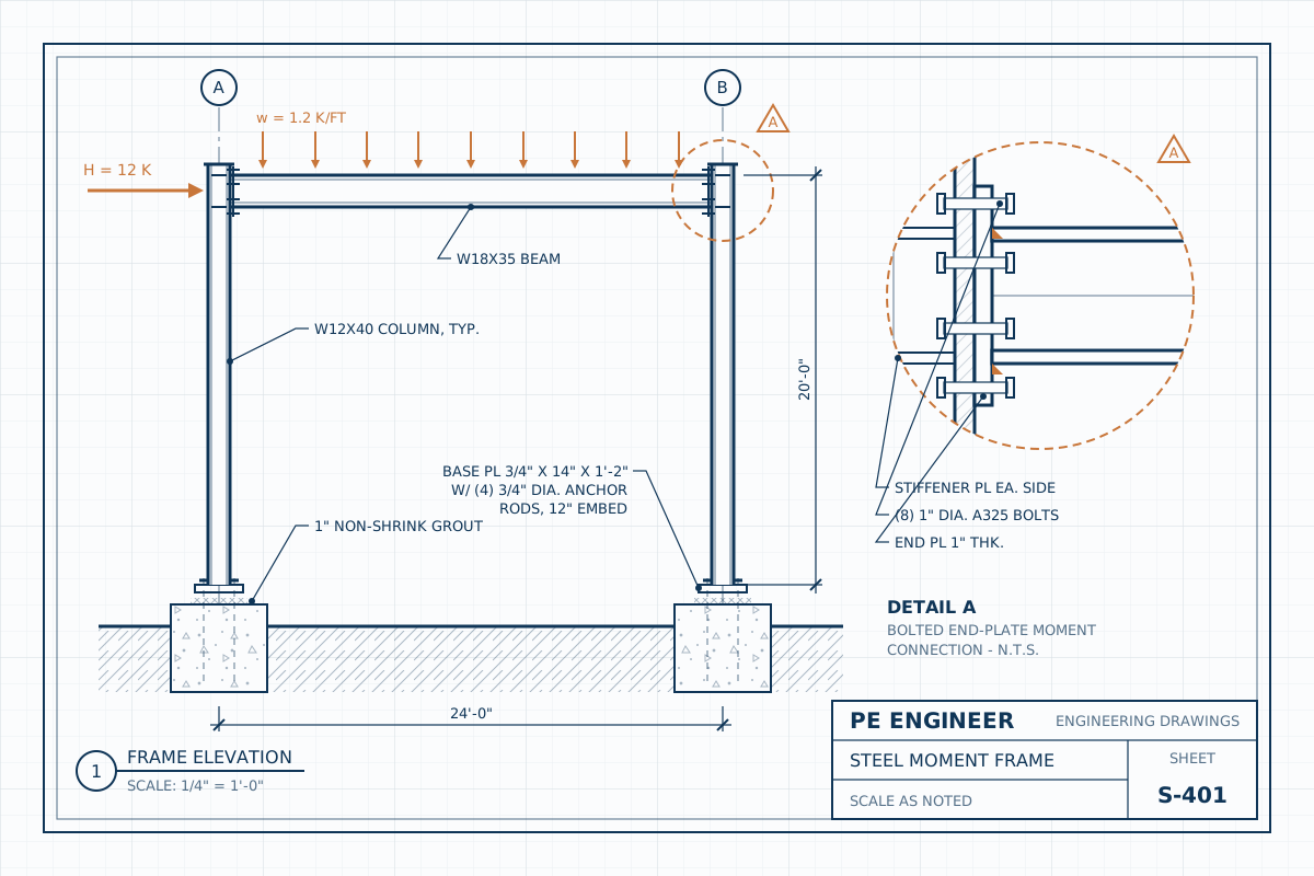 Steel Structure DesignSteel beams, columns, moment frames, braced frames and connections designed to AISC standards and stamped for residential, commercial and industrial permits.View service
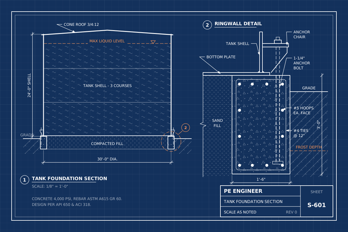 Tank & Skid FoundationsRingwalls, mat foundations and anchorage for storage tanks, plus concrete pads for skids, compressors and generators, designed and sealed by a licensed PE.View service
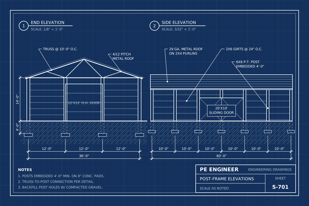 Pole Barns & Metal BuildingsStamped pole barn plans, post-frame shops and garages, barndominiums and foundations for pre-engineered metal buildings, designed for your snow and wind loads.View service
Frequently asked questions
Can my existing building support an overhead crane?
Sometimes. It depends on the column and frame sizes, connections and foundations, and on the crane’s capacity and service class. Many buildings were designed only for roof, snow and wind loads. We evaluate the existing structure with the crane loads added and tell you whether it works as-is, needs reinforcing, or calls for a freestanding runway.
What information do you need from the crane supplier?
Rated capacity, span, maximum wheel loads and spacing, crane and trolley weights, CMAA service class, type of control and rail size. If the crane is not purchased yet, we can design for typical data and verify once the supplier provides final numbers.
Do you design the crane itself?
No. The crane, hoist and trolley are designed and supplied by the crane manufacturer under CMAA and ASME standards. We design the runway girders, rails, columns, brackets, monorail beams and foundations that support the crane, using the manufacturer’s loads.
Why does crane runway deflection matter so much?
Excess vertical or horizontal deflection lets the crane wheels climb, skew or bind on the rails, which accelerates wear and can create safety hazards. Industry guidance sets tighter limits for runway girders than for ordinary beams, and the limits tighten further for cranes in heavier service classes.
Can you design a foundation for a freestanding jib crane?
Yes. Freestanding jibs produce a large overturning moment at the base, so we design a reinforced footing or verify a slab and anchorage for the manufacturer’s base reactions. We check existing slab thickness and concrete strength before relying on it.
Do hoist beams need to be load tested?
Testing and marking requirements depend on the type of equipment and the applicable OSHA rules and ASME B30 standards. We provide the rated load and design basis on the drawings, and your crane or hoist service provider can perform the testing and inspection those standards call for before use.